Ethernet frame: definition and variants of the frame format
In an Ethernet network, devices share data using packets. They contain, among other things, the Ethernet frame, which is divided into several data sets. These records consist of binary code that provides important information, such as addresses, control information, payload data, and checksums.
Depending on the Ethernet standard, Ethernet frames are structured differently and may contain more or fewer data fields, depending on the network protocol.
When transmitting data over Ethernet, the Ethernet frame is primarily responsible for the correct rulemaking and successful transmission of data packets. Essentially, data sent over Ethernet is carried by the frame. An Ethernet frame is between 64 bytes and 1,518 bytes big, depending on the size of the data to be transported.
In the OSI model the frame is on the data link layer and is responsible for the error-free transmission and separation of the bit stream into blocks. The first version of Ethernet (Ethernet I) was still based on 16-bit data fields without defined bytes. Modern Ethernet frames were first used in the Ethernet II structure, before the IEEE (Institute of Electrical and Electronics Engineers) developed the standard protocol IEEE 802.3 (first IEEE 802.3raw) in 1983.
Following technical advancements, the frame structure was adapted several times so that the frames could carry more defined data. With the IEEE 802.3 format, the basic MAC frame and the SNAP frame were created for the multiplexing process and for manufacturer-related identification data. For the development of the VLAN, the Ethernet II frame and the Ethernet IEEE 802.3 frame were developed as "tagged" variants. These tags contain control data that can assign the frame to a specific VLAN.
Ethernet II
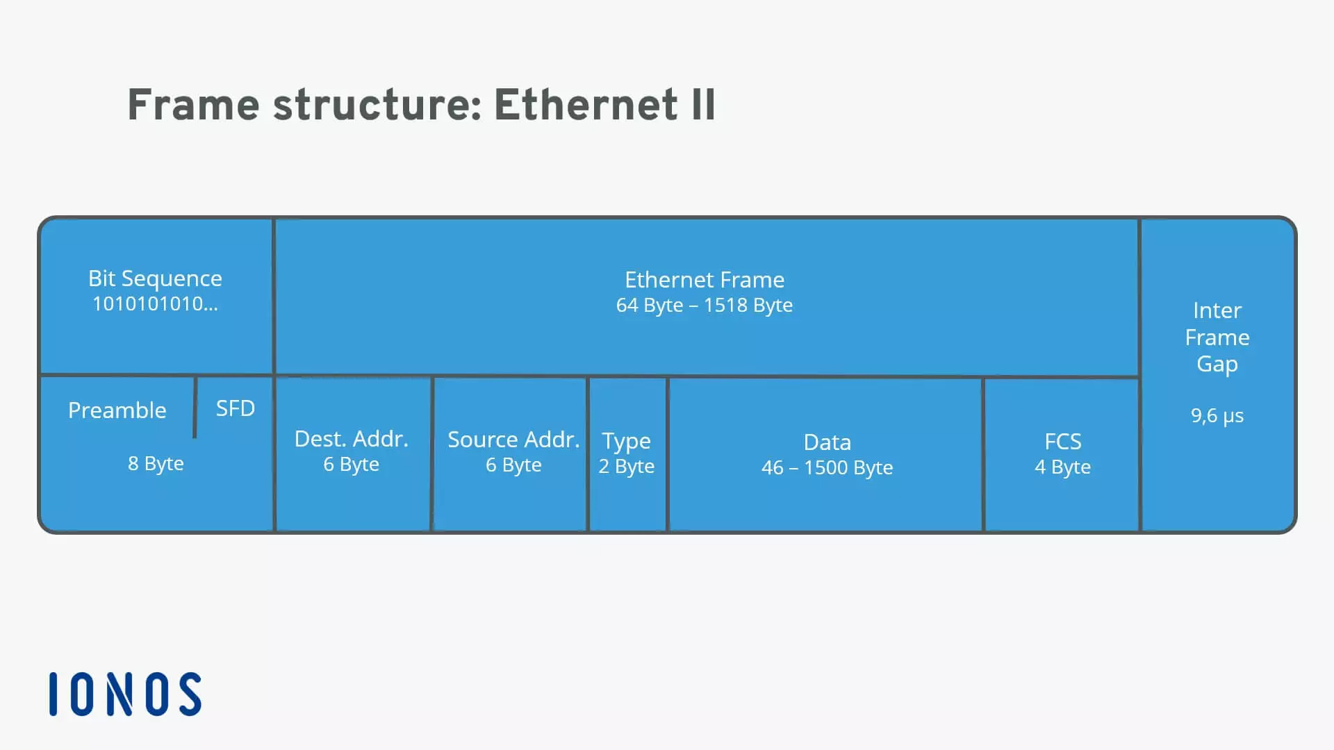
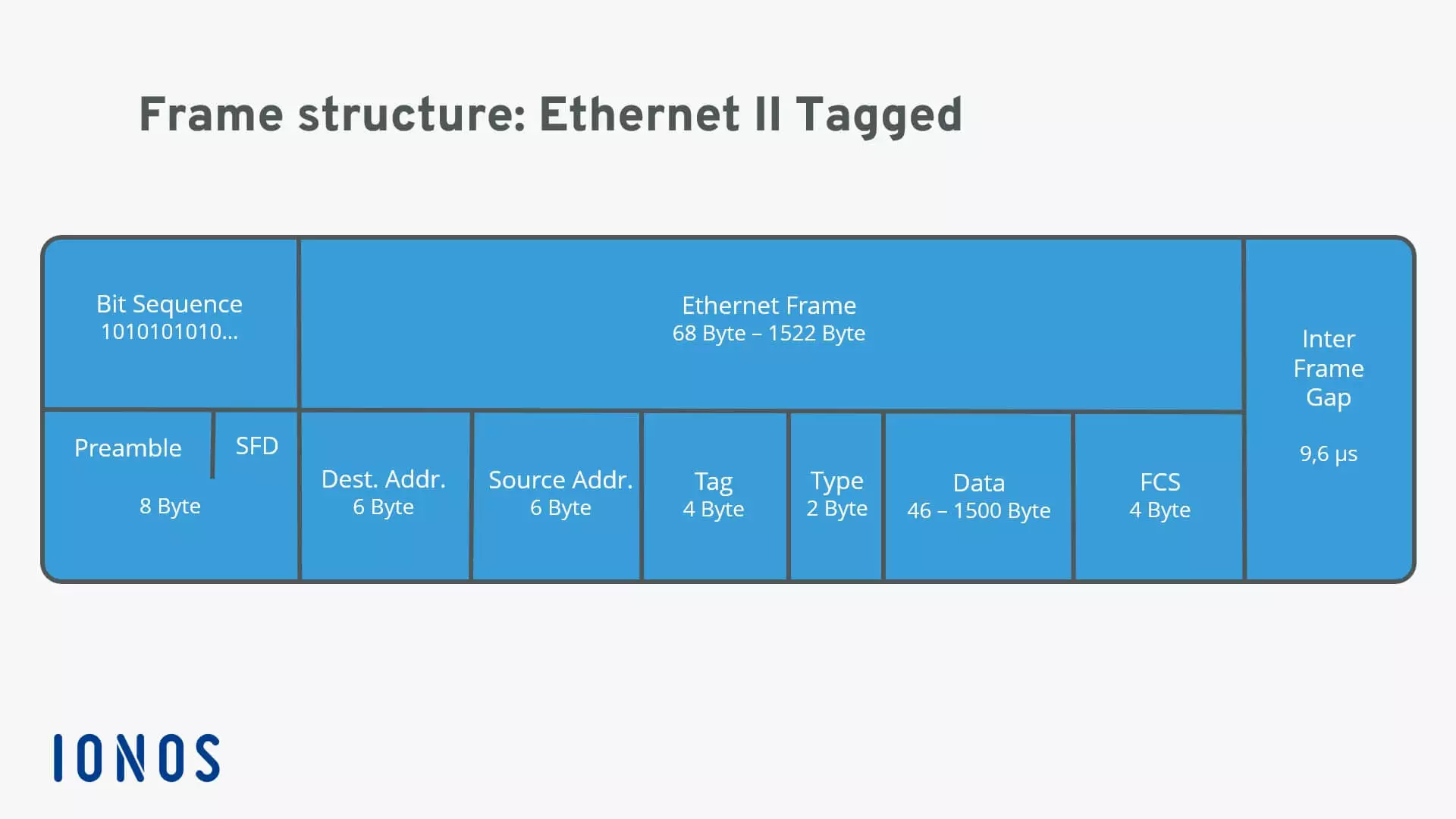
An Ethernet frame must be at least 64 bytes for collision detection to work, and can be a maximum of 1,518 bytes. The packet starts with a preamble that controls the synchronization between sender and receiver and a "Start Frame Delimiter" (SFD) that defines the frame. Both values are bit sequences in the format “10101010 ...” in which the actual frame contains information about source and destination addresses (MAC format), control information (in the case of Ethernet II the type field, later a length specification), followed by the transmitted data record. A frame check sequence (FCS) is an error-detecting code that closes the frame (except for the preamble and SFD). The packet is completed by an "Inter Frame Gap," which defines a 9.6 μs transmission pause.
Ethernet II uses the classic frame structure with a type field ("Type") which defines various protocols of the network layer. In the OSI model, the network layer is important for connecting and providing network addresses. The type field was replaced by a length specification in later frame formats.
In the type field, Ethernet II determines which switching protocols are used. This is important for segmenting the data stream and preventing data congestion.
The Ethernet II frame was defined in 1982 and has formed the foundation of all subsequent frame developments. However, the format still enjoys great popularity, primarily because it gives the data field the most space (up to 1,500 bytes).
Ethernet 802.3raw
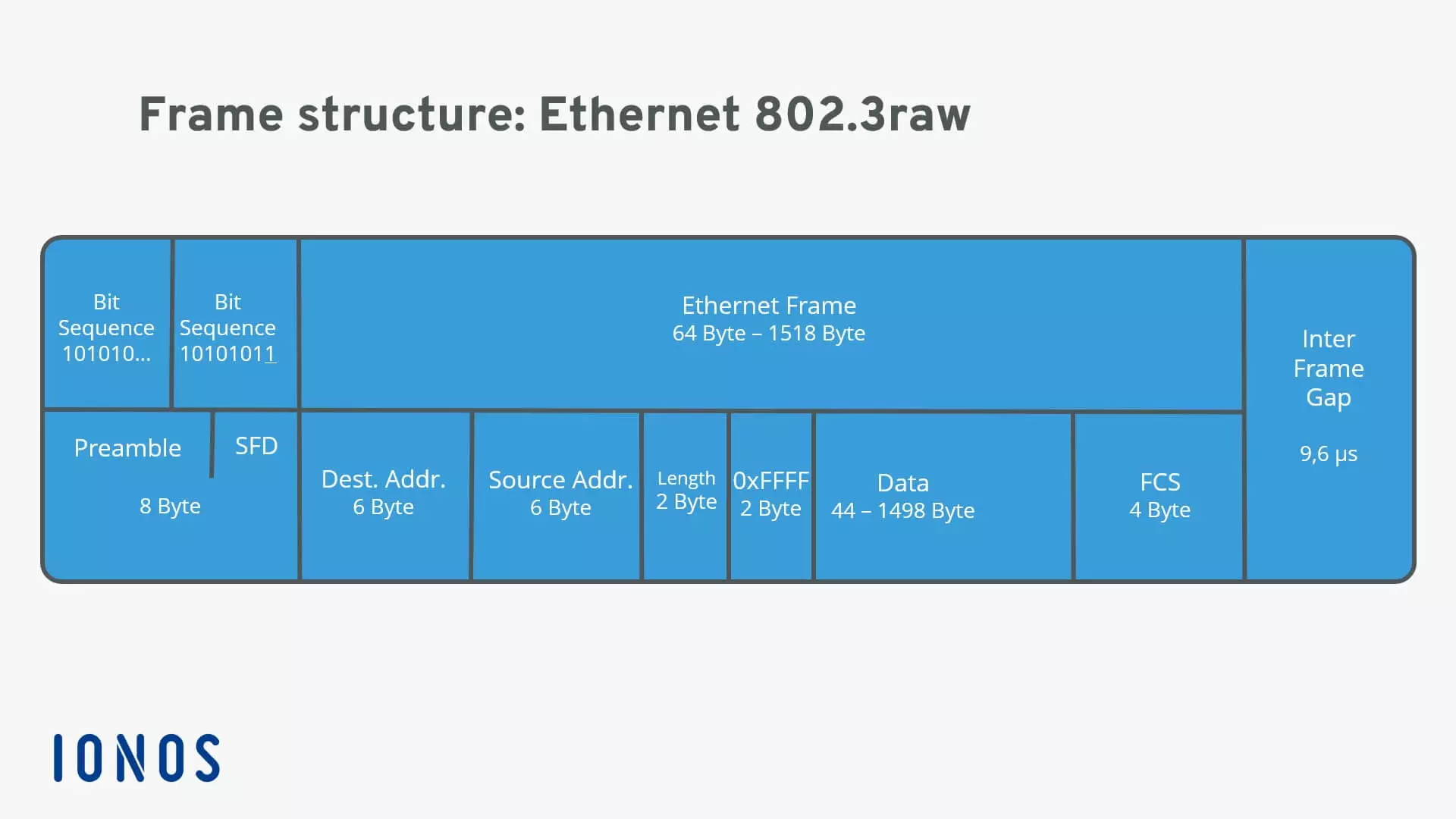
This rough version of the 802.3 packet, given the unfortunate name "Ethernet 802.3," was brought out by Novell before widespread establishment of IEEE 802.3 standards and the popular IPX/SPX protocol, unfortunately leading to frequent confusion with the IEEE standard. Consequently, Novell added "raw" to the name. In contrast to the classic Ethernet II model, this frame defines an exact end to the bit sequence for the SFD. This identifies the data packet as the 802.3 standard for the receiver. 802.3raw frames do not contain a protocol identifier, as they are only usable for Novell IPX. In addition, the data to be transmitted is always prefixed with 2 bytes, which always consist of ones. This is the only way to distinguish a "raw" frame from other frames in the 802.3 family.
The IEEE 802.3raw frame can only be used for the IPX protocol, because the type field's protocol ID is missing. The name "IEEE 802.3raw" is also slightly misleading, since Novell used the protocol name without involving the IEEE in the development of the frame. The use of this frame means extra work for the user, because compatibility issues can arise between devices. From 1993 onwards, Novell itself recommended the "Ethernet 802.2" standard, which used the IEEE 802.3 frame, to avoid the likelihood of confusion with the "raw" frame.
Ethernet IEEE 802.3
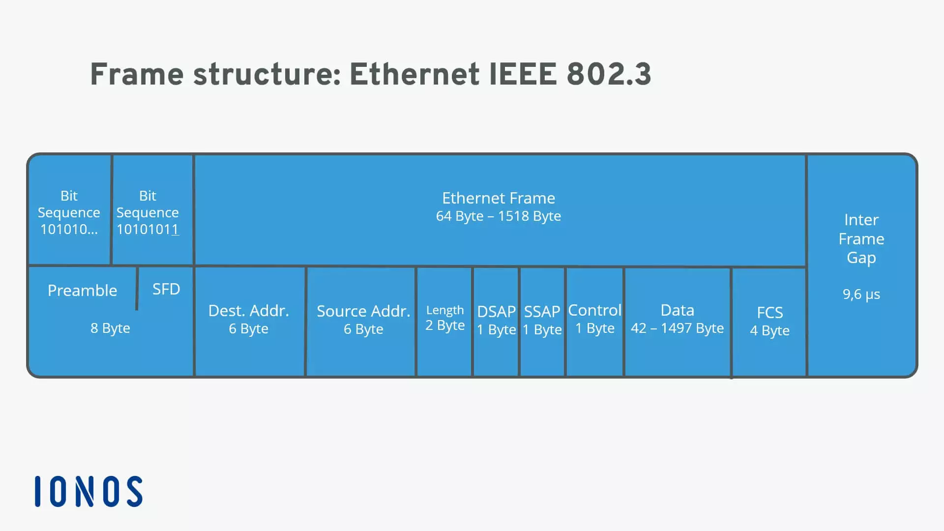
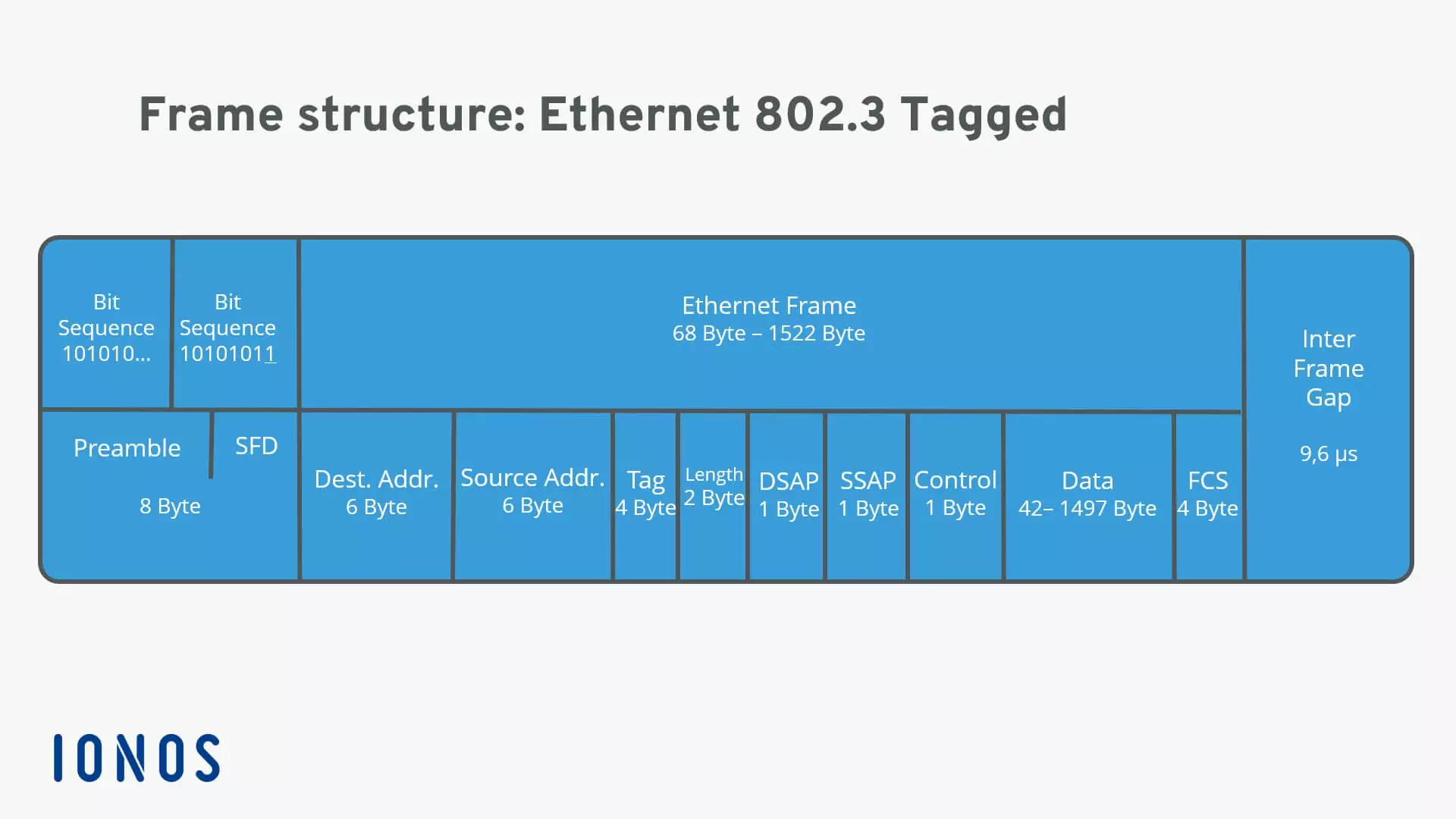
This standardized version of the Ethernet 802.3 frame can define up to 256 compatible protocols, with important protocol information integrated into the data field. In addition, the "Destination Service Access Point" (DSAP) and "Source Service Access Point" (SSAP) are included. The new control field defines the "Logical Link" (LLC) of the protocol. This point ensures the transparency of the media sharing procedures and can control the data flow.
Ethernet IEEE 802.3 is by far the most popular and widely used LAN frame structure today. However, some networks and protocols require more space for specific information. Consequently, there are variants of the IEEE 802.3 frame that provide additional data blocks for specific information, among them the SNAP extension and the VLAN tag.
Ethernet IEEE 802.3 SNAP
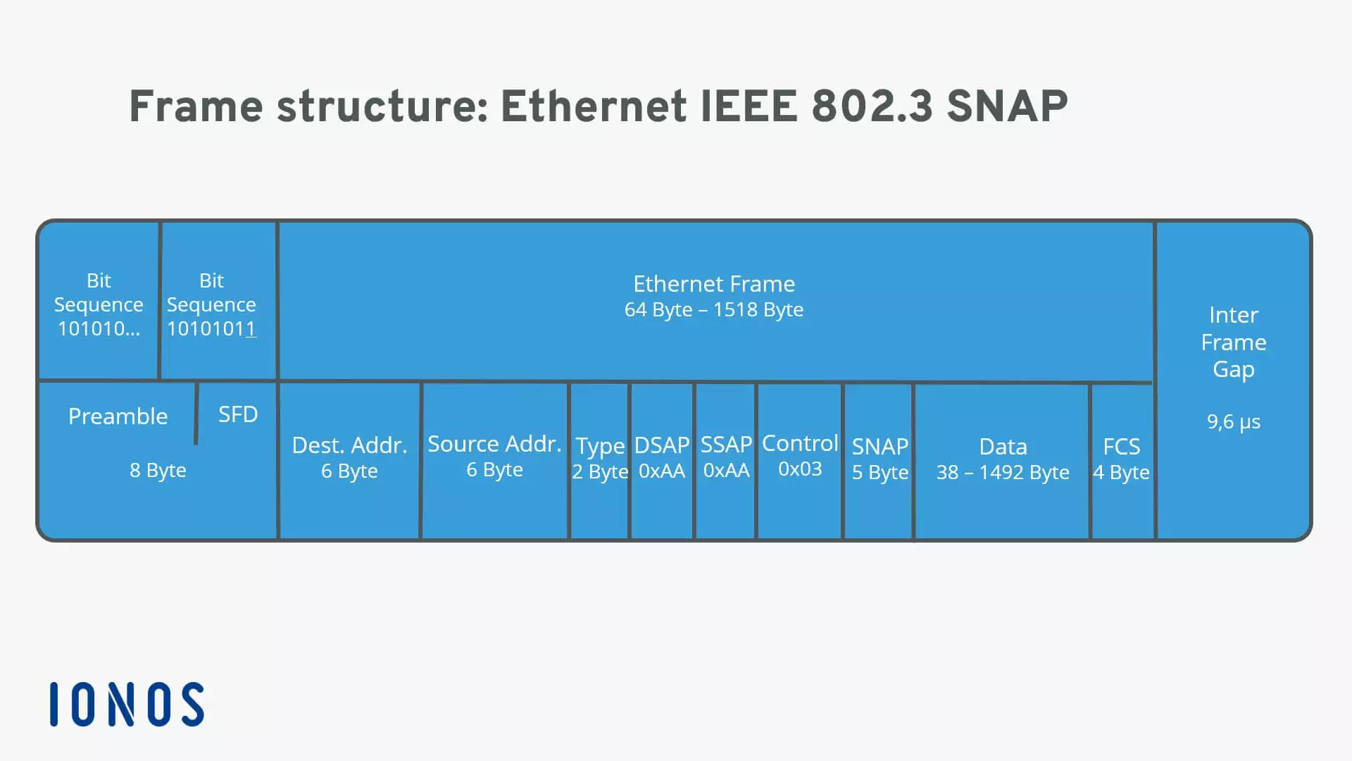
The SNAP field (“Sub Network Access Protocol”) is useful for defining more than 256 protocols. To do this, 2 bytes are made available for the protocol number. In addition, the manufacturer can integrate a unique identifier (3 bytes). Unlike its predecessors, SNAP also ensures backward compatibility with Ethernet II. DSAP, SSAP, and Control are firmly defined here.
With the newly added space for protocol information, IEEE 802.3 SNAP is extremely versatile and makes compatibility between numerous different protocols in a network possible. However, the space for the actual data is slightly less.
VLAN 802.1q - Ethernet II tagged and IEEE 802.3 tagged
Tagged frames contain a so-called VLAN tag for them to be assigned to a virtual local area network (VLAN), which separates the network structure into physical and logical levels. This means that with the help of VLANs, subnetworks can be implemented without having to install hardware. The subnetwork is then virtual and not physically realized. Identifying Ethernet frames within a VLAN requires the “Tag” field. On a physical level, VLANs work through switches.
In the OSI model, a VLAN works on the data link layer (layer 2) and controls the data flow control. With VLAN, networks can become more efficient by being divided into subnets. For the information that the switch handles, the tagged frames are responsible. In the Ethernet II frame, the “Tag” field is implemented before the “Type” field and uses 4 bytes. This increases the minimum size of the Ethernet II frames by 4 bytes.
VLAN tags can also be installed in today's most popular IEEE 802.3 frame format. Within this frame, the “Tag” field uses 4 bytes and is implemented before the length specification. The minimum size of the frame is now increased from 4 bytes to 68 bytes.
Overview: Ethernet frame blocks
| Building block | Size | Function |
|---|---|---|
| PreambleStart frame delimiter (SFD) | 8 bytes | Synchronization of the receiversBit sequence that initiates the frame |
| Destination address (MAC) | 6 bytes | Hardware address of the destination network adapter |
| Source address (MAC) | 6 bytes | Hardware address of the source network adapter |
| Tag | 4 bytes | Optional VLAN tag for integration in VLAN networks (IEEE 802.1q) |
| Type | 2 bytes | Ethernet II: labeling of layer 3 protocols |
| Length | 2 bytes | Length information about the record |
| Destination service access point (DSAP) | 1 byte | Individual address of the addressed service access point |
| Source service access point (SSAP) | 1 byte | Source address of the sending device |
| Control | 1 byte | Defines the LLC frame (logical link) |
| SNAP | 5 bytes | Field for the definition of the organizationally unique identifier (OUI) of the manufacturer and the protocol number (like "Type") |
| Data | 44-1,500 bytes (limit depending on frame structure) | The data to be transmitted |
| Frame check sequence (FCS) | 4 bytes | Checksum that computes the entire frame |
| Inter frame gap (IFS) | - | Transmission break of 9.6 μs |


